AI World at Electrify10x
Home Page
News & Updates
AI Playground
HostMetro
Zopto
HostMetro
Alfred
Dux-Soup
Klenty
Mailrush
Content Studio
Stripo Email
LambdaTest
Cable Sizing Calculator
September 19, 2023
[wpaicg_form id=2997 custom=yes]
Previous
Next
More From My Blog
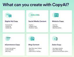
Copy.ai
May 9, 2023
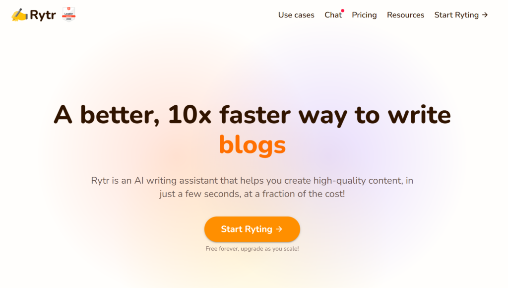
Rytr.me
May 9, 2023
Writesonic
May 9, 2023